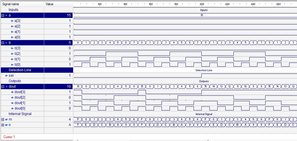
Design A 4 Bit Adder Subtractor
Design a 4-bit adder/subtractor circuit with add/sub control line Adder bit subtractor verilog using vhdl structural code waveform modeling gate cum xor output style 4bit programming Adder subtractor bit circuit carry ripple four logic add truth control line sub overflow diagram complement detection addition table designing
Please, design a 4-bit binary adder-subtractor. Your | Chegg.com
Please, design a 4-bit binary adder-subtractor. your Adder subtractor binary circuit bit diagram coa logic block javatpoint mode Vhdl programming: design of 4 bit adder cum subtractor using structural
Adder bit four subtractor ripple ppt powerpoint presentation slideserve
Adder subtractor bit binary please electrical engineering get chegg answers questions .
.


Design a 4-bit adder/subtractor circuit with add/sub control line

COA | Binary Adder-Subtractor - javatpoint

VHDL Programming: Design of 4 Bit Adder cum Subtractor using Structural

PPT - Four-Bit Adder- Subtractor PowerPoint Presentation - ID:4278806